Conway's Game Of Life in BlinkScript (because why not)

I’ve finally started toying around with BlinkScript. After multiple unsuccessful attempts at understanding the Blink Reference Guide, I am now faced with an interesting enough challenge that I went back to it, for real. I’ve also started working with Guillem Ramisa De Soto, which, to be honest, feels like a huge cheat code (i r winner).

I’m not too far on my journey to mastering the power of the node, but I’m at least confident that I now understand the language well enough to work with it.

So, when I watched Veritasium’s video about math being flawed this weekend, I naturally had to try making Conway’s Game Of Life in BlinkScript.
And so, here it is:

The Setup

feedback_loop_screenshot.png

The main problem of Conway’s Game Of Life is that you need to know the current state of the cell at t to generate the next cells at t+1. On it’s own, that’s perfectly reasonable but you can’t really do that in Nuke. So, I had to render each frame to feed them back to the script via a time offsetted read, thus creating a feedback loop.

The comp looks like that.

Feedback loop logic

  • At frame == 1

    • Render Frame 1

  • At frame >= 2

    • Load frame-1 via the read and the framehold [frame-1] nodes

    • Go through the BlinkScript Node to get the state of the game at frame based on the state of the game at frame-1

    • Render it and start again for frame+1

The Code

kernel TheGameOfLife : public ImageComputationKernel
{
    Image src; 
    Image dst;

    param:
        // Color above which a pixel will be consider as alive
        float whitePoint;

    void init()
    {
        // To get the neighbouring pixels
        src.setRange(-1, -1, 1, 1);
    }

    void process(int2 pos)
    {

        float neighbours[9];
        int neighboursCount = 0;

        // Loop on every pixels neighbouring the current one
        int index = 0;
        for (int i = -1; i <= 1; i++) {
            for (int j = -1; j <= 1; j++) {
                neighbours[index] = src(i, j);
                index += 1;
            }
        }
        // Neighbouring pixel coordinates
        // (-1,  1) - (0,  1) - (1,  1)
        // (-1,  0) - (0,  0) - (1,  0)
        // (-1, -1) - (0, -1) - (1, -1)

        // Count the number of neighbouring pixels that are alive
        // Do not count the current pixel to avoid self reference and messed up results
        for (int i = 0; i <= 9; i++) {
            if (i != 4) {
                if (neighbours[i] > whitePoint) {
                    neighboursCount += 1;
                }
            }
        }

        // Output based on the rules of the game
        dst() = 0.0f;

        // Current is alive
        if (neighbours[4] > whitePoint) {
            if (neighboursCount > 3) {
                // Any live cell with more than three live neighbours dies, as if by overpopulation.
                dst() = 0.0f;
            } else if (neighboursCount >= 2) {
                // Any live cell with two or three live neighbours lives on to the next generation.
                dst() = 1.0f;
            } else if (neighboursCount < 2) {
                // Any live cell with fewer than two live neighbours dies, as if by underpopulation.
                dst() = 0.0f;
            }
        // Current is dead
        } else {
            if (neighboursCount == 3) {
                // Any dead cell with exactly three live neighbours becomes a live cell, as if by reproduction.
                dst() = 1.0f;
            }
        }
    }
};

Have fun with it !

Normalize and Blend expressions

Another personal reminder note so that I can actually remember how to do this without having to spend a few dozen minutes googling it…

Normalizing values between 2 bounds

Normalize between 0 and 1

$${x' = \frac{x - \min{x}}{\max{x} - \min{x}}}$$

Normalize between -1 and 1

$${x'' = 2\frac{x - \min{x}}{\max{x} - \min{x}}-1}$$

Normalise between a and b

$${x''' = (b-a)\frac{x - \min{x}}{\max{x} - \min{x}} + a}$$

Nuke node

NoOp { name NormaliseValues selected true xpos -5265 ypos 718 addUserKnob {20 User} addUserKnob {7 val} val 1 addUserKnob {7 minval} minval 0 addUserKnob {7 maxval} maxval 10 addUserKnob {26 "" +STARTLINE} addUserKnob {7 upperbound} upperbound 1 addUserKnob {7 lowerbound} addUserKnob {26 "" +STARTLINE} addUserKnob {7 result} result {{"(upperbound-lowerbound) * ((val - minval) / (maxval - minval)) + lowerbound"}} }

Blend 2 values

With w : [0;1] $$x=Aw + B(1-w)$$

Nuke node

NoOp { name BlendValues selected true xpos -5080 ypos 784 addUserKnob {20 User} addUserKnob {7 val1 R -10 10} addUserKnob {7 val2 R -10 10} val2 1 addUserKnob {7 blender} blender 1 addUserKnob {26 "" +STARTLINE} addUserKnob {7 result R -10 10} result {{"val2 * blender + val1 * (1-blender)"}} }

Extend Format to Bounding box, restore original Format.

This more a personal reminder than anything else but I thought I might as well store it here instead of my notes.

This is intended to ease the use of notes and gizmos that handle out of format pixels poorly. It extends the format to the whole boundingbox and then restores it to its original size, allowing you to do whatever needs doing in the middle.

Read More

Edit a Spherical Map in Nuke

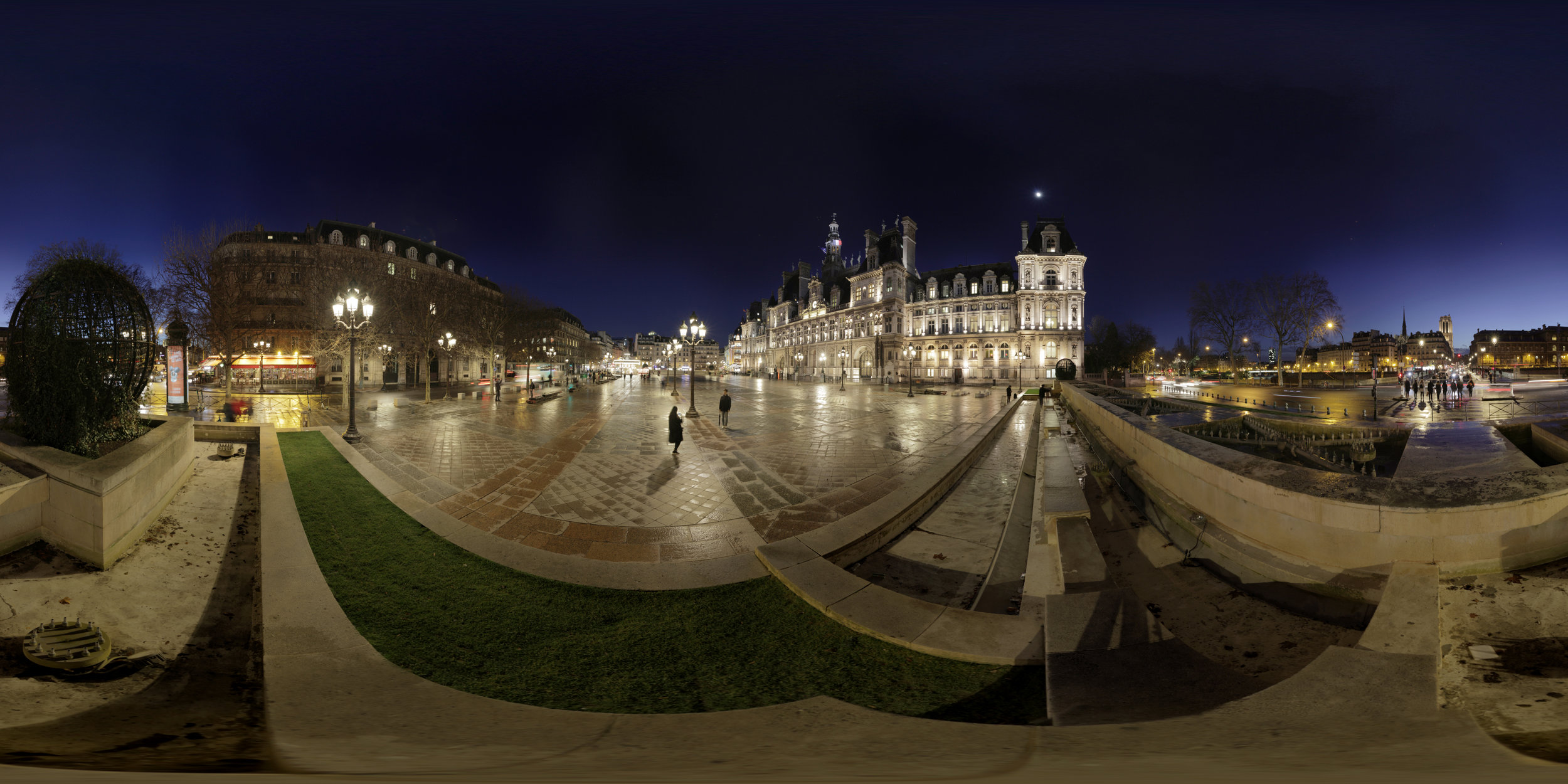
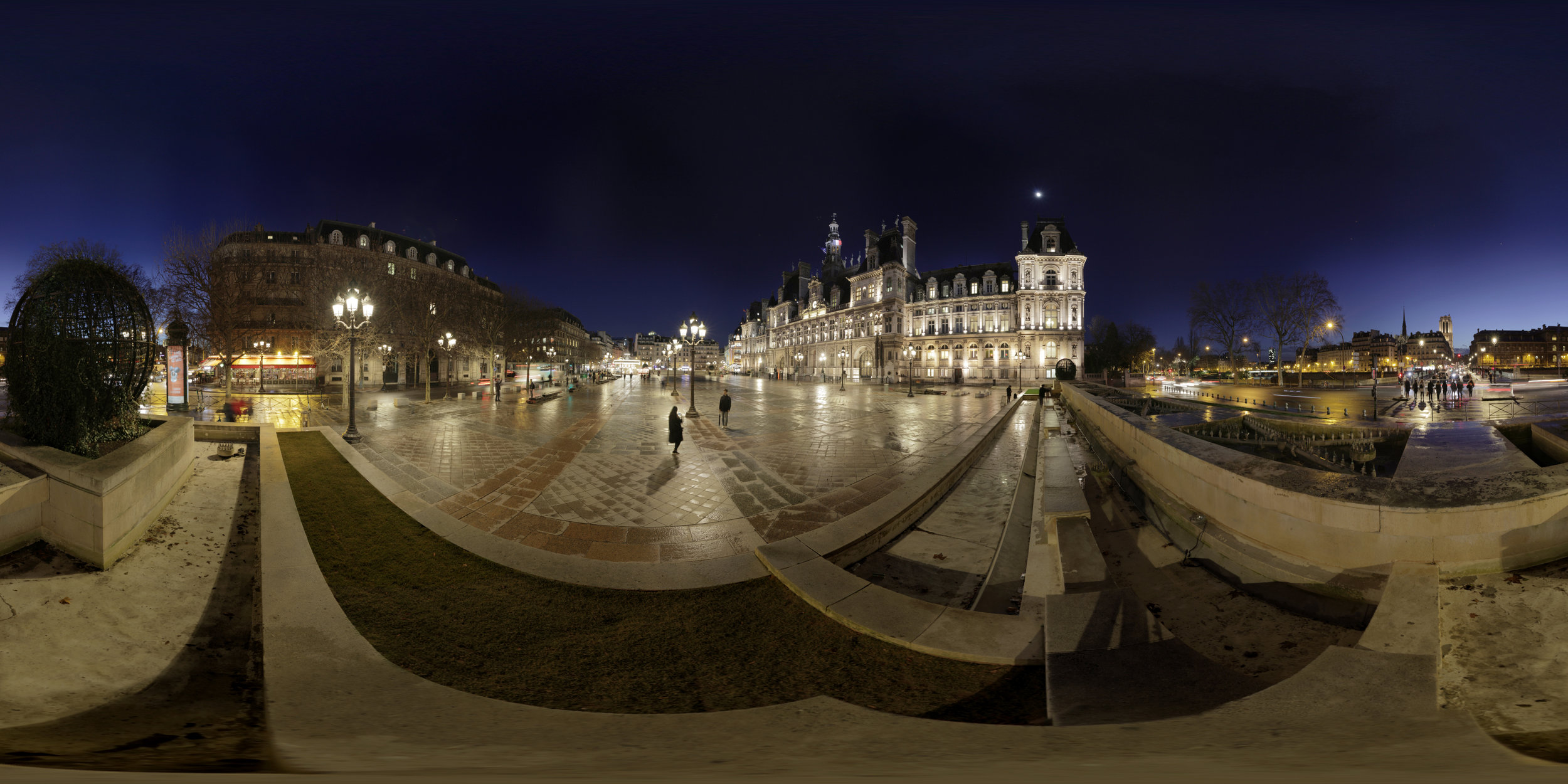
I was recently talking to a colleague interested in VR about 360 spherical maps. He was telling me that editing the maps in nuke wasn't as easy as it is in After Effect. So I made something !

The idea is to take an equirectangular map, remap it to the six square faces of a cube, make the edit and then re-render the result as an equirectangular map.

The trick is to link the SphericalTransform and the related card values so that if SphericalTransform2’s ry is 90, Card2’s rotate y is also 90, 180 on the third, and so on. For the top and bottom faces the rotation is on x.

In the file bellow, I’ve taken the liberty to set the SphericalTransform format to 1/4 of the input map’s width. It' seemed like a good idea seeing how you need 4 faces to go from 1 edge to the other. I didn’t spent that much time on it so the formats are not dynamically set and you’ll have to adjust them to your needs.

You can download the comp file here.

I’ve created a clean copy/paste file without Nuke’s version line so with should be pastable anywhere.


Here is a quick edit of the bottom half of the spherical map, made relatively easily as I was working on a non deformed image.

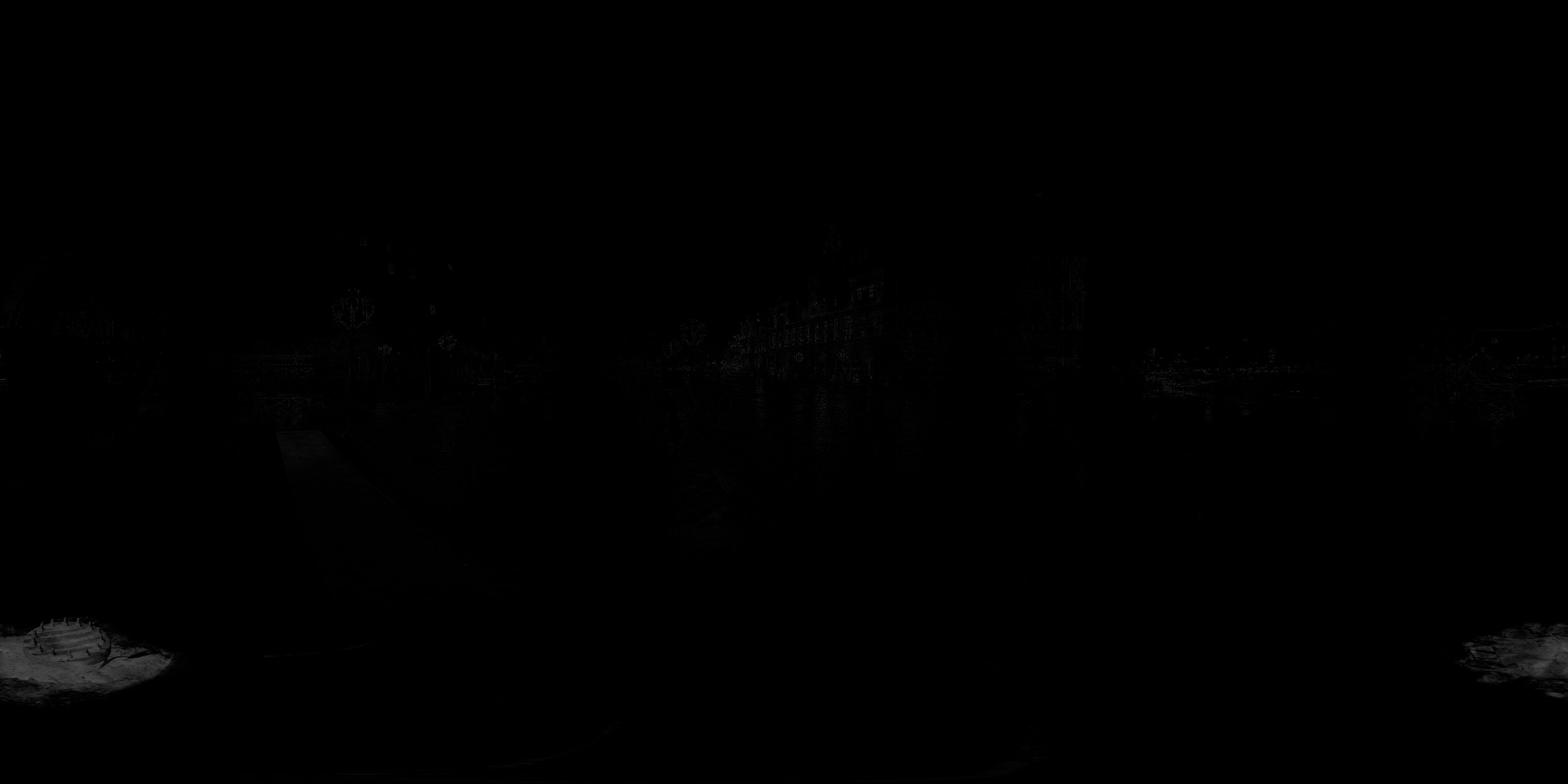
As we can see on the difference map, we unfortunately have some light difference even where I didn’t made any edits. Those are due to the SphericalTransform filtering and the render. I found that Impulse results in the less difference.

Python - sRGB to Linear / Linear to sRGB

A quick note to just so I can keep track of the functions.

def srgb2lin(s):
    if s <= 0.0404482362771082:
        lin = s / 12.92
    else:
        lin = pow(((s + 0.055) / 1.055), 2.4)
    return lin


def lin2srgb(lin):
    if lin > 0.0031308:
        s = 1.055 * (pow(lin, (1.0 / 2.4))) - 0.055
    else:
        s = 12.92 * lin
    return s

Note that I picked up these functions somewhere on stackoverflow, I didn’t come up this any of it…

Replacing a specular pass in comp

I woke up today with a question floating in a skype conversation with can more or less be translated as :

If I create a sphere in Nuke
plug an HDR map
with the wP, can we make a "fake spec"?
with the Hdr?

Which made me think of a technique I made up last year, more or less day for day, as I needed to replace the reflections on the front lenses of a pair of binoculars. I didn't ask about the specifics of today's question but I can only guess that they are the same as the ones that prompted me to do what I will explain below.

The problem was that a specific part of an object needed to display a reflection of the 3D environment. This would not come up if you were doing direct reflexions or at least using a map of your 3D set as a reflexion map; but can happen when you are using a generic spherical hdri for whatever reason (cost and simplicity in our case).

Solution

The solution I came up with is utilizing the relight node.

spec_relight1.png

As shown in FIG. I am plugin an Environment light in the Relight node, with a Specular material.

  • The Relight node is left with default parameters, I've only ticked use alpha.

  • The Environment node as some interesting parameters. Color, intensity and blur size directly affect the output look while mirror image and rotate affect the position on the environment map.
    (I've chose to handle the rotations using a SphericalTransform)

  • The Specular shader is pretty important. Leaving white at 1 will render the correct colors. Min shininess and max shininess affect the look of the specular, and to be perfectly franc, I'm not sure how. I chose to not use them and went below the interface minimum values by setting them to 0; this renders a perfect reflection on the whole surface.

The next step is more or less just a matter of replacing the rendered specular pass. Here I used to rendered pass to make a mask before merging my new reflexion on top of the diffuse pass. You could choose not to use a mask of the previous pass and utilize the min shininess and max shininess values instead. How you want to merge the new reflexion is heavily dependent on the look you're after.

Results

On the short clip below, I've displayed the original render, a render of my comp and a render of the same 3D scene that gave the original render but with the environment what I've used in nuke, to serve as a comparison.

I also opted to not replace the indirect specular as most of it was the result of rays hitting the ground.

It is obviously not as good as finding a solution utilizing your render engine and all its physicality but it's fairly quick and decent looking.

I've made the comp available for download here : download the comp.